EMC电磁兼容和可靠性分析仪器、仪表、设备综合服务供应商
芯片级、板级、系统级ESD静电抗扰和EMI电磁干扰测试方案定制商

SmartScan-350/550 EMI是一款专门设计的电磁干扰扫描系统
Amber Precision Instruments (API)电磁扫描分析仪利用电场和磁场探棒逐点探测无线通讯终端、集成电路、汽车电子、IC芯片及显示器等器件和整机产品的电磁场,得到相应测试区域的电场、磁场的相对值或绝对值,以分析电磁辐射干扰情况。
该方案能为实现自动测试和手动测试
|
型号 |
ESD-350 |
ESD-550 |
|
扫描仪图片 |
|
|
|
款式 |
桌面式 |
独立式 |
|
探头定位 (1) |
350mm 4轴机械手 |
550mm 4轴机械手 |
|
Z向行程 |
150mm |
150mm |
|
最大扫描区域 |
1500cm2 |
4150cm2 |
|
精度 |
100um |
100um |
|
重复性 |
< 50um |
< 50um |
|
占用空间 |
27" x 25" x 37" (WxDxH) |
59" x 33" x 72" (WxDxH) |
|
频率限制 |
6 GHz |
18 GHz |
35+ GHz |
|
|
|
标准探头组 (1): ⦁ Hx-2mm (3.5 MHz to 10 GHz) ⦁ Hx-5 (1 MHz to 4 GHz) ⦁ d=4mm Hz (1 MHz to 4 GHz) |
标准探头组 + ⦁ Hx-1mm (5 MHz to 18 GHz) ⦁ Ez-3mm (5 MHz to 18 GHz) ⦁ d=2mm Hz (5 MHz to 10 GHz) |
标准探头组+
⦁ Hx-0.1mm
(up to 40 GHz) |
|
|
驱动
其他硬件 |
20 MHz ~ 6 GHz, Gain=16dB at 2 GHz (2) |
Amps can be provided at additional costs. |
||
|
一个SA 模块 (3) |
一个SA模块 | 一个SAm | ||
|
EMI SW |
EMI SW |
EMI SW |
||
|
线缆和连接器 |
线缆和连接器 |
高频线缆和连接器 |
||
|
|
标准的MEI扫描仪 |
18 GHz 可选组件 |
35 GHz 可选组件 |
|
不同形状的多个扫描区域
等距扫描
•在通过扫描高度分配从参考z高度固定距离扫描的情况下
•通过两种方式从DUT组件高度进行恒定距离扫描
o使用触摸传感器–探头接触到DUT表面后,它将使用户缩回
确定高度,进行测量,然后移至下一个扫描点
o定义多个扫描区域并为每个扫描区域分配高度–用户定义
每个扫描区域的DUT表面上方所需的扫描高度。 DUT高度可以是
使用触摸传感器一键获得。
距参考表面固定距离距DUT表面恒定距离
不同形状的多个扫描区域
与基准面保持固定距离 与被测器件表面保持恒定距离
灵活的扫描结果显示
•3D
•最大振幅与频率
•每个扫描点的频谱
Hx越过显示峰和分钟的迹线
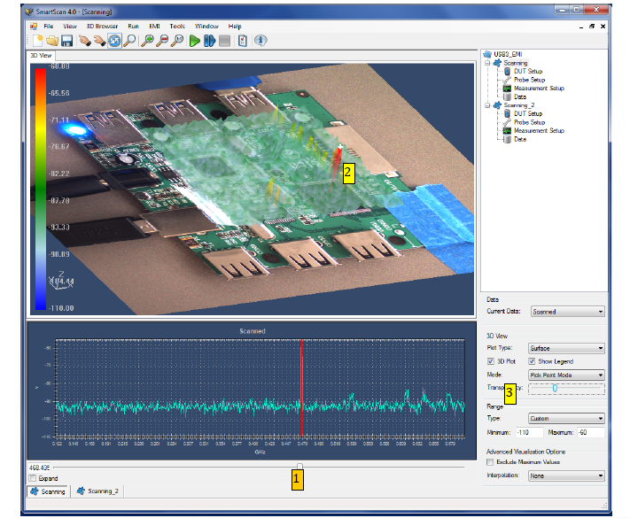
(1)上图显示的频率指示条
(2)显示在DUT上测得的峰值幅度
(3)显示透明条使您可以查看DUT图像在实测场强下
⦁多层显示和“剖面图”

-多层可以一起显示
-左侧-未应用“剖切面”; 正确–应用XZ“剖切面”后
选件
低频探头组
测量频率越低,探头尺寸越大。 但是,API有
开发了低频探头套件,仅使用2〜3 mm的探头尺寸即可测量低至50 kHz。
• Hx-2mm-LF: 20 kHz ~ 20 MHz
• Hz-2mm-LF: 20 kHz ~ 20 MHz
• Ex-2mm-LF: 20 kHz ~ 20 MHz
• Ez-2mm-LF: 20 kHz ~ 20 MHz
窄带探头
与窄带探头相比,API的窄带探头在窄带处的增益高出7〜10 dB
常规探头
•GSM-860M:以860 MHz为中心
•GSM-1950M:以1950 MHz为中心
•WiFi-2400M:以2400 MHz为中心
*联系API以获取自定义探针*
近场计算
SA以dBm或dBV为单位给出扫描结果。 为了扩大近场的利用信息,将dBm或dBV转换为场
(A / m或V / m)是必不可少的EMI扫描仪能力。 API提供必需的软件和硬件套件,
用于系统因子提取和计算领域。
|
频率限值
软件
其他硬件
|
6 GHz |
18 GHz |
35 GHz |
|
一个SA模型&
|
一个SA模型&
|
一个SA模型&
|
|
|
EMI 软件 |
EMI 软件 |
EMI 软件 |
|
|
50欧姆微带 |
共面波导 |
高频共面波导
|
|
|
电缆和连接器 |
电缆和连接器 |
高频电缆和连接器
|
offering precise control of probe landing points and high speed scan. SmartScan EMI supports standard test of IEC 61976-3 and following core features;
• Wide range of probe selection
o EMI measurement from below 50 kHz to over 35 GHz
- Low frequency probe set: 50 kHz ~ 50 MHz with 2mm probe dimension
- Narrow band probes: GSM (860 MHz, 1950 MHz), WiFi (2400 MHz), etc.
- Custom probes
• Integrated camera to take DUT pictures
- Scan points (or areas) are defined over the DUT picture
- Image stitching for larger DUT's
- Scan results are displayed over the DUT picture automatically
• Layout file importing
- ODB files can be imported, and scan points can be defined over the layout layer
• Flexible Scan Area Editor (SAE) module
- Multiple scan areas with different scan resolutions
- Points, lines, rectangles, any shape of scan area
• Automatic electrical X-Y offset correction
• Touch sensor to detect component heights
• Continuous run of multiple projects
• Flexible display options
- 3D, multiple layer, cut-planes, histogram, merging multiple scan results to one display
• Customizable report generation in MS Word or Excel
• Matlab support
• Wizard to assist step by step scan condition set-up
• Optional emission scan technologies include
o Field calculation
o Phase measurement
o Near field to far field transformation (available with phase measurement option)
o Shielding effectiveness evaluation (SEE) package
Hardware Configurations:
|
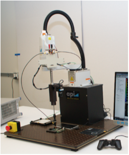
Models |
EMI-350 |
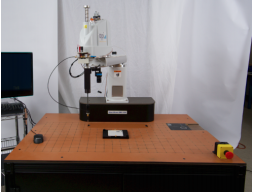
EMI-550 |
|
Scanner Images |
|
|
|
Styles |
Table top unit |
Stand-alone unit |
|
Probe positioning (1) |
350mm four axis robot |
550mm four axis robot |
|
Z-stroke |
150mm |
150mm |
|
Max. scan area |
1500cm2 |
4150cm2 |
|
Accuracy |
100um |
100um |
|
Repeatability |
< 50um |
< 50um |
|
Dimensions |
27" x 25" x 37" (WxDxH) |
59" x 33" x 72" (WxDxH) |
Notes: (1) Contact API for other sizes of robots
Packages by Frequency Ranges
|
Freq. Limit |
6 GHz |
18 GHz |
35+ GHz |
|
Probes |
Standard probe set (1): ⦁ Hx-2mm (3.5 MHz to 10 GHz) ⦁ Hx-5 (1 MHz to 4 GHz) ⦁ d=4mm Hz (1 MHz to 4 GHz) |
Standard probe set + ⦁ Hx-1mm (5 MHz to 18 GHz) ⦁ Ez-3mm (5 MHz to 18 GHz) ⦁ d=2mm Hz (5 MHz to 10 GHz) |
Stand probe set + 18 GHz probe set + ⦁ Hx-0.1mm (up to 40 GHz) ⦁ Ez-HF (up to 40 GHz) |
|
Amps
Other HW |
20 MHz ~ 6 GHz, Gain=16dB at 2 GHz (2) |
Amps can be provided at additional costs. Contact API with specifications |
|
|
One SA model (3) |
One SA model |
One SA model |
|
|
EMI SW |
EMI SW |
EMI SW |
|
|
Cables and connectors |
Cables and connectors |
High frequency cables and connectors |
|
|
|
Standard EMI scanner |
18 GHz optional package |
35 GHz optional package |
(1) Under common NF measurement set-up conditions – 100KHz RBW, at Room Temp,
60dB lower gain extrapolation from the peak of frequency response and 0dBm source
power over a 50 Ohm micro-strip line. See the probe characterization report file for
more details.
(2) Two 16dB (@2GHz) 20MHz ~ 6GHz amplifiers
(Other amplifiers are available upon request. Additional charges may apply)
(3) SmartScan supports most SA’s from KeySight, Tek, R&S or LeCroy
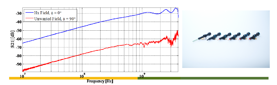
Probes
API designs, builds and characterizes each probe in house (adaptors to mount non-API-built
probes can be supplied). Wide band, high sensitivity and high frequency are very important,
however, suppressing unwanted component is as important. API’s probes have at least 20dB
separation between wanted and un-wanted components.
Software Highlights
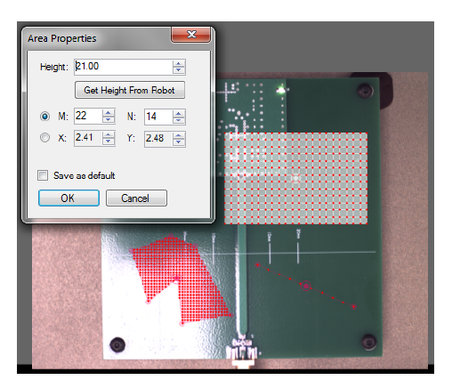
Scan area editor (SAE)
• By an integrated camera- The scan area is edited directly on the DUT picture taken by the
camera. The software controls the movement of the probe to the defined scan points
• Flexible scan area selection - any shape and multiple scan areas can be defined for optimum
scan time. Height of each defined scan area can be given separate.
Multiple scan areas in different shapes
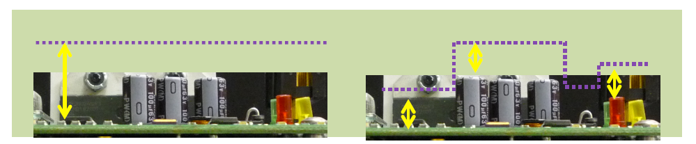
Constant distance scan
• At a fixed distance scan from a reference z-height by scan height assignment
• Constant distance scan from DUT component heights in two ways
o Using the touch sensor – As soon as the probe touches the DUT surface, it retracts user
defined height, takes the measurement, then move to next scan point
o Defining multiple scan areas and assigning heights to each scan area – The user defines
the desired scan height above the DUT surface of each scan area. The DUT height can be
obtained by one click using the touch sensor.
At a fixed distance from a reference surface At a constant distance from DUT surface
Multiple scan areas in different shapes
At a fixed distance from a reference surface At a constant distance from DUT surface
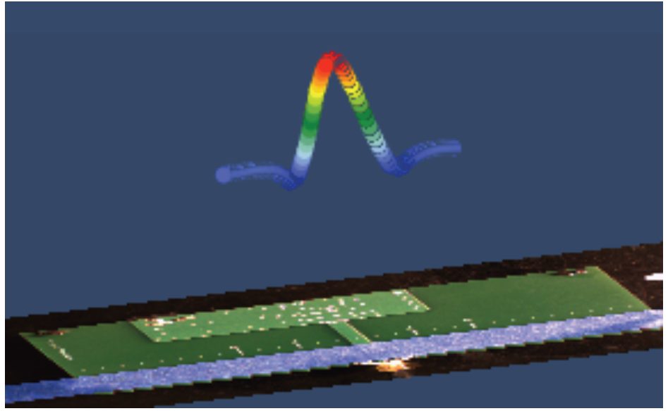
Flexible scan results display
• 3D
• Max amplitude vs. frequency
• Frequency spectrum of each scan point
Hx crossing a trace showing peak and mins
(1) The frequency indication bar that upper plot shows
(2) It shows where the peak magnitude measured on the DUT
(3) The display transparency bar enables view of the DUT image
under the measured field magnitude
⦁ Multiple layer display and ‘cut-planes’
- Multiple layers can be displayed together
- Left – no ‘cut-plane’ applied; right – after XZ ‘cut-plane’ applied
Options
Low frequency probe set
The lower the frequency to measure, the larger the probe size becomes. However, API has
developed low frequency probe sets that are capable of measuring down to 50 kHz with only 2~ 3 mm probe sizes.
• Hx-2mm-LF: 20 kHz ~ 20 MHz
• Hz-2mm-LF: 20 kHz ~ 20 MHz
• Ex-2mm-LF: 20 kHz ~ 20 MHz
• Ez-2mm-LF: 20 kHz ~ 20 MHz
Narrow band probes
API's narrow band probes have 7~10 dB higher gain at narrow band compared with similar size
conventional probes
• GSM-860M: Centered at 860 MHz
• GSM-1950M: Centered at 1950 MHz
• WiFi-2400M: Centered at 2400 MHz
* Contact API for custom probes *
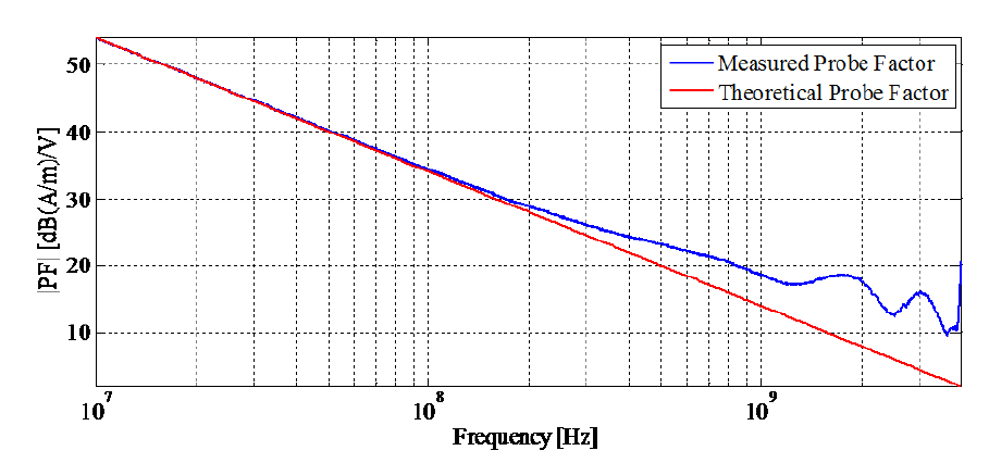
Field calculation
SA gives the scan results in dBm or dBV unit. In order to expand the utilization of the near field
information, converting dBm or dBV to fields (A/m or V/m) is a must-have EMI scanner
capability. API provides required SW and HW kits for system factor extraction and calculation
of fields.
|
Freq. Limit Drivers
SW
Other HW |
6 GHz |
18 GHz |
35 GHz |
|
One SA model & one VNA model |
One SA model & one VNA model |
One SA model & one VNA model |
|
|
EMI SW |
EMI SW |
EMI SW |
|
|
50 Ohm micro-strip |
Coplanar Waveguide |
High frequency Coplanar Waveguide |
|
|
Cables and connectors |
Cables and connectors |
High frequency cables and connectors |
某某婚礼策划
在线QQ:12345678
在线QQ: 12345678
中国某某某有限公司版权所有 沪ICP备12345X78号
COPYRIGHT 2008-2014 WWW.XXXXXX.COM.CN ALL RIGHTS RESERVED
上海市XXXX房产有限公司 沪ICP备020XXXX号 版权所有
Copyright 2016 Global Electronic AG
TeL:0731-85782021 E-mail:Billion.xiao@glb-et.com
湖南格雷柏电子科技有限公司 版权所有
上海市·某某某区·某某某路·某某某大厦·某某层
COPYRIGHT 2008-2014 WWW.XXXXXX.COM.CN ALL RIGHTS RESERVED
上海市XXXX房产有限公司 沪ICP备020XXXX号 版权所有