EMC电磁兼容和可靠性分析仪器、仪表、设备综合服务供应商
芯片级、板级、系统级ESD静电抗扰和EMI电磁干扰测试方案定制商
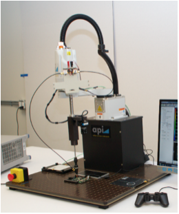
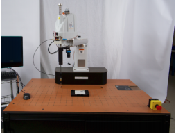
SmartScan-350/550 ESD是一款专门设计的静电敏感度扫描系统
来自(TLP)脉冲源的宽带脉冲被传送到电场或磁场探头。生成的场与DUT或PCB板上的组件或线路耦合,并导致故障。或者可以通过直接注入探头直接注入脉冲。扫描系统主要再现了IEC 61000-4-2试验失效类型,包括软失效和硬失效。
静电敏感度智能扫描测试系统
SmartScan-350/550 ESD是一款专门设计的静电敏感度扫描系统
来自(TLP)脉冲源的宽带脉冲被传送到电场或磁场探头。生成的场与DUT或PCB板上的组件或线路耦合,并导致故障。或者可以通过直接注入探头直接注入脉冲。扫描系统主要再现了IEC 61000-4-2试验失效类型,包括软失效和硬失效。
探头由具有软件控制的机器手定位在所需的测试点,触发耦合,并记录被测器件的响应以进行相对抗扰度水平比较。简化的抗扰度设置图和抗扰度示例图(敏感性图)如下所示。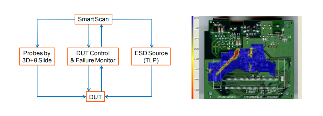
ESD抗扰度扫描仪的应用
根据IEC 61000-4-2型式试验确定敏感的点、区域或痕迹
开发初期系统级ESD测试性能评估
设计变更前后相对抗扰度水平比较
选择更多防静电零部件(供应商A优于B)
硬件配置参数
型号 | ESD-350 | ESD-550 |
扫描仪图片 |
|
|
款式 | 桌面式 | 独立式 |
探头定位 (1) | 350mm 4轴机械手 | 550mm 4轴机械手 |
Z向行程 | 150mm | 150mm |
最大扫描区域 | 1500cm2 | 4150cm2 |
精度 | 100um | 100um |
重复性 | < 50um | < 50um |
占用空间 | 27" x 25" x 37" (WxDxH) | 59" x 33" x 72" (WxDxH) |
静电探头 (2) | Hx/y – 1mm and 5mm Ez – d=8mm | Hx/y – 1mm and 5mm Ez – d=8mm |
注意: (1) 其他尺寸的机械手联系我们
(2) 其他尺寸的探头联系我们
静电盒
静电盒由TLP传输线脉冲和故障检测单元组成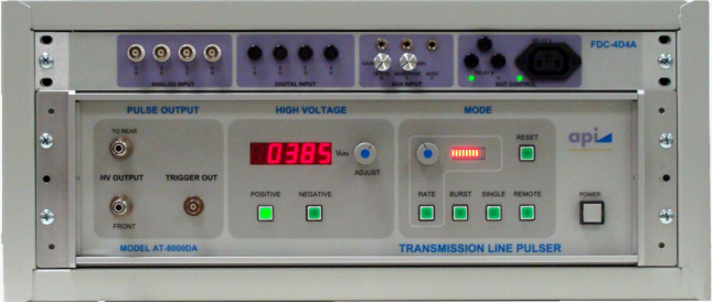
故障检测单元
四个模拟信号输入
四个数字信号输入
三辅助输入
远程控制DUT电源循环用120V和DC电源
用于图像变化检测的光学传感器
用于声音开/关检测的微型电话
DUT控制器的集成
多信号同时监测
监测信号的布尔运算,以控制被测器件的复位和故障类型的分类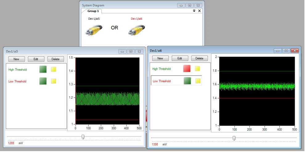
TLP传输线脉冲
200V至8,000V传输线充电电压
<300 ps的上升时间和> 6 ns的下降时间,以防止在两个边缘引起故障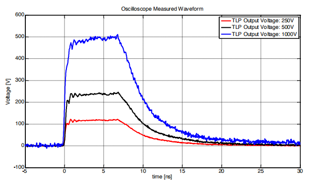
软件
ESD测试条件控制和数据可视化
人性化,直观且非常灵活,可集成其他扫描技术
扫描区域编辑器(SAE)
通过DUT定位相机-可以直接在相机拍摄的DUT图片上编辑扫描区域。
该软件控制探头移动到定义的扫描点
灵活的扫描区域选择-可以定义任何形状和多个扫描区域以获得扫描时间。 每个定义的扫描区域的高度可以分别指定
对于大型DUT,需要拍摄多张图片并将它们拼接在一起,以便在一幅图片中捕获整个DUT图像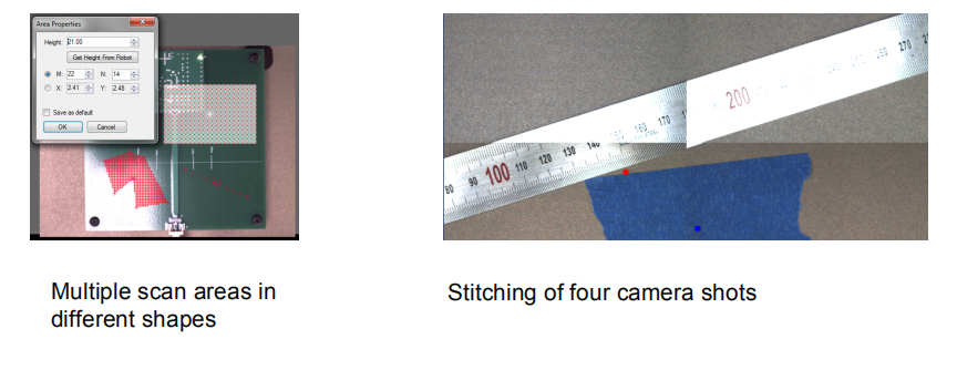
定义的不同形状的多个扫描区域 四张相机镜头拼接成一张图片
SmartScan-350/550 ESD is specifically designed for susceptibility scanning system.
A broad band pulse from a pulse source (TLP) is delivered to an electric field or a magnetic field probe. The generated field couples with components or traces of DUT or PCB, and causes failure. Or the pulse can be directly injected through direct injection probes. It mainly reproduces IEC 61000-4-2 test failure types, both soft and hard failures.
The probe is positioned at desired test points by a robot with software control, triggers the coupling and the response of the DUT is recorded for relative immunity level comparison. A simplified immunity set-up diagram and a sample immunity level plot (susceptibility map) are shown below.
Applications of the immunity scanning are
Identification of sensitive spots, areas or traces to IEC 61000-4-2 type tests
Estimation of system level ESD test performance at early stage of development
Relative immunity level comparison before and after design change
Selection of more ESD resistant parts (supplier-A over –B)
Hardware Configurations:
Models | ESD-350 | ESD-550 |
Scanner Images |
|
|
Styles | Table top unit | Stand-alone unit |
Probe positioning (1) | 350mm four axis robot | 550mm four axis robot |
Z-stroke | 150mm | 150mm |
Max. scan area | 1500cm2 | 4150cm2 |
Accuracy | 100um | 100um |
Repeatability | < 50um | < 50um |
Foot print | 27" x 25" x 37" (WxDxH) | 59" x 33" x 72" (WxDxH) |
ESD Probes (2) | Hx/y – 1mm and 5mm Hz – d=8mm Ez – d=8mm | Hx/y – 1mm and 5mm Hz – d=8mm Ez – d=8mm |
Notes: (1) Contact API for other sizes of robots
(2) Contact API for other probes
ESD Box
ESD Box consists of TLP and failure detection unit
Failure detection unit
Four analog signal inputs
Four digital signal inputs
Three auxiliary inputs
120V and DC power supplies for remote controlled DUT power cycle
Optical sensors for image change detection
Micro phone for sound On/Off detection
Integration of DUT controllers
Simultaneous monitoring of multiple signals
Boolean operation of monitoring signals to control DUT reset and sort out failure types
TLP (Transmission Line Pulsar)
200V to 8,000V transmission line charging voltage
<300 pSec rise time and >6 nSec falling time to prevent causing failures at both edges
Software
ESD test condition control and data visualization
User friendly, intuitive and very flexible to integrate other scan technologies
Scan area editor (SAE)
By a DUT location camera- The scan area is edited directly on the DUT picture taken by the camera. The software controls the movement of the probe to the defined scan points
Flexible scan area selection - any shape and multiple scan area can be defined for optimum scan time. Height of each defined scan area can be given separate
For large DUT's, multiple pictures are taken and they are stitched together to capture whole DUT image in one picture
某某婚礼策划
在线QQ:12345678
在线QQ: 12345678
中国某某某有限公司版权所有 沪ICP备12345X78号
COPYRIGHT 2008-2014 WWW.XXXXXX.COM.CN ALL RIGHTS RESERVED
上海市XXXX房产有限公司 沪ICP备020XXXX号 版权所有
Copyright 2016 Global Electronic AG
TeL:0731-85782021 E-mail:Billion.xiao@glb-et.com
湖南格雷柏电子科技有限公司 版权所有
上海市·某某某区·某某某路·某某某大厦·某某层
COPYRIGHT 2008-2014 WWW.XXXXXX.COM.CN ALL RIGHTS RESERVED
上海市XXXX房产有限公司 沪ICP备020XXXX号 版权所有

